Analyze and Document Geometric Tolerances Directly on 3D CAD Models
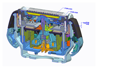
Variety may be the spice of life, but wide-ranging variation in physical dimensions, properties or space between parts is the last thing you want when the components of your product must fit together correctly. You want your parts and assemblies to be within certain tolerances, or acceptable degrees of variation.
Creo Tolerance Analysis Extension (TAE), powered by CETOL Technology, is an extension to Creo Parametric. With Creo TAE you can evaluate the impact of tolerances and dimensioning on product designs before the product reaches either prototyping or manufacturing.
Creo TAE provides two analysis tools: worst-case analysis and statistical analysis. Worst-case analysis, often used for critical components, considers what happens when each of the components in the stack-up reaches the maximum acceptable measurement. In statistical analysis each component’s variation is modeled as a statistical distribution. These distributions then are added together to predict the distribution of the assembly measurement.
Using these tools, designers can produce products that meet customer requirements within acceptable margins. The result: shorter product development cycles, lower product cost, and higher product quality.
Creo GD&T Advisor for MBD
Creo Parametric 4.0 is your go-to release for model-based definition. There are a ton of new features for realizing a MBD model. Refer to the following free downloads :
- MBD E-book
- 5 Steps to Get You Started with MBD
- Benefits and Barriers to Model-Based Definition
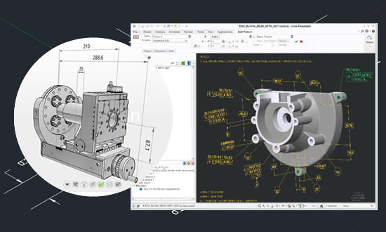
Creo GD&T Advisor is an extension to Creo Parametric 4.0 that provides expert guidance on the application of GD&T and validation that it has been done correctly. When the model is complete, you can be confident that it complies with the relevant standard and is fully constrained. Creo GD&T Advisor also improves your productivity when applying GD&T, reducing the number of mouse clicks and time required to apply and validate GD&T. It also simplifies the understanding of the complex GD&T standards by providing readily available guidance during every step of the application process. Rulesets included are ASME Y14.5-2009, ISO 1101-2012, and their associated standards.
In a drawing centric world, the non-geometric attributes (GD&T) that are required to manufacture the products, such as dimensions, tolerances, datums, etc., are on the 2D Drawing. However, in an MBD world this non-geometric information, that is critical for downstream Manufacturing and Inspection processes, must be contained within the model in a clear and un-ambiguous way.
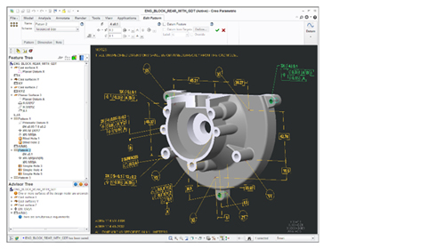
Key benefits of GD&T Advisor
- Increases productivity
- Reduces costs
- Provides consistency
- Eliminate mistakes due to human error
- Improve design communications, reducing the chance of misinterpreted or ambiguous information
In this blog post, I’ll highlight some of the key features of Creo GD&T Advisor:

Creation
- Feature-centric workflow guides the user
- Fast creation of annotations
Validation
- Complies with ASME and ISO standards
- Fully constrains the model geometry
Education
- Feature-centric workflow guides the user
- Fast creation of annotations
Creo GD&T Advisor reduces the error between as-designed assemblies and as-produced products through intuitive modeling technologies and advanced visualization techniques. The functional Feature Centric GD&T provides for:
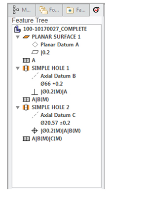
Tolerance (Functional) Feature
- Geometric elements are classified by function
Workflow
- Define the tolerance feature
- Determine tolerance scheme
- Determine tolerance values
- GD&T Advisor creates annotations
Guidance Provided
- Filtered UI
- Recommended options
- Not-permissible options
- Advisor Tree
- Errors and Warnings
- Color coding
- Visual feedback on completeness of tolerance definition


