What Is Topology Optimization? A Primer for Design Engineer
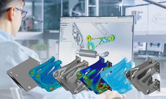
Have you come across images of exotic, organic looking part shapes in CAD graphics windows? Do they look like flights of fancy, rather than disciplined work? These shapes may be the result of a topology optimization study. This type of application is now readily available – so you can try your hand!
In a sense these shapes are indeed flights of fancy. However, they originate not from a human mind, but rather from the determined logic of a computer algorithm.
Topology optimization takes a 3D design space and literally whittles away material within it to achieve the most efficient design. The method doesn’t care about aesthetics, traditional approaches, or any other of the usual design constraints that you would normally use in design. At its simplest level, if you define the loading and the constraint system, it will figure out the material needed to develop that load path.
Behind the scenes
The technology behind this magic starts with a very regular finite element analysis (FEA) mesh occupying the design space you have defined. An initial FEA will show the stress distribution throughout this design space, but also show which regions are working efficiently.

Each element reports back its stress level and strain energy; essentially, how hard is it working. Those elements which are not picking up much stress and have little strain energy are doomed. The topology optimizer will remove them from the mesh.
However, as it removes these elements it will keep an eye on whether the overall evolving structure is affected by their departure. In some cases, the elements may be reprieved.
The topology optimizer has a target number of elements to get rid of. This is based on the target volume fraction you set. If you aim for a fraction of 30%, then you are sending 70% of the elements in a regular mesh to the chopping block. In practice, the removal of elements won’t be attempted in one hit. The target volume fraction will be approached in steps. At each step the distribution of elements will iterate so that the stress state stabilizes.
The kill zone
In many optimizers the action is slightly subtler than this. Deleting elements from the mesh at each step is technically complicated and computationally expensive.
Instead of using this “hard kill” method, the system takes a “soft kill” approach. The element stiffness is dropped down to a near chewing gum level. The density is dropped in a similar manner. The element is still there, but it has been marginalized.
Many optimizers further relax this strict segregation between the parent materials, let’s say steel (with a relative density 1.0) and chewing gum (with a relative density close to 0.0). An element can adopt any stiffness and density across a range between these two limits. However, each element is “encouraged” to migrate to a value of 1.0, or 0.0 –with a big penalty if it is caught sitting between.
Shades of grey
In many cases, optimizers won’t be able to achieve the limiting values of 1.0 or 0.0 for all elements. Some will end up with some value in between. So, what does it mean to have the relative material property in an element set to 0.8?
It doesn’t represent anything physically, but to the optimizer it represents the most efficient distribution of material. Using a grayscale to represent material distribution will show regions of parent material in white (1.0) and chewing gum in black (0.0), and shades in between
If the optimizer is struggling, then large regions of the resulting configuration will be varying shades of grey. If the optimizer can find a well-defined load path, then the distribution will be clearer, migrating towards black or white.
So where does the exotic shapes come from that I described in the introduction? They do not represent the element faces, instead they are surfaces fitted through the grey-scale contours. The smoothness of the surfaces is very largely controlled by how fine the underlying FEA mesh is and how well distributed the parent material is.
You are in control
Topology optimization is sometimes described as a wild ride! It is great at coming up with radical solutions – the flights of fancy as I call them. However, there are many controls available to the engineer to help steer towards more usable configurations.
These include manufacturing constraints, such as limiting the size of members within the design space, dictating that components must be symmetric about planes, or extrudable, or can be drawn from a mold, and so on. By choosing the volume fraction you can control how aggressive the optimizer will be.
I have many hints and tips on how to approach topology optimization and get the best out of it. I will be sharing those in upcoming articles.